Product Categories

Thermal Mass Flow Meter
MODEL: TMF1600 Series
Flange thermal gas mass flow meter is one of kind mass flow meter which Is popular in industrial applications is the way they are designed and built. The feature is no moving parts, nearly unobstructed straight through flow path, require no temperature or pressure corrections and retain accuracy over a wide range of flow rates. Straight pipe runs can be reduced by using dual-plate flow conditioning elements and installation is very simple with minimal pipe intrusions. Flange thermal gas mass flow meter size from DN10~DN2000mm
Contact us


info@cbroindia.com sales@cbroindia.com

Sales Support
+917021306718
Technical Support
+918591988100
Advantages
Flange thermal gas mass flow meter advantanges :
(1)Wide range ratio 1000:1;
(2)Large diameter, low flow rate, negligible pressure loss;
(3)Direct mass flow measurement without temperature and pressure compensation;
(4)Very sensitive for low flow rate measurement;
(5)Easy to design and select, easy to install and use;
(6)Suitable for all kinds of single or mixed gas flow measurement Could measure gas with flow velocity from 100Nm/s to 0.1Nm/s, which can be used for gas leak detection;
(7) No pressure loss or very small pressure loss.
Application
Flange thermal gas mass flow meter application:
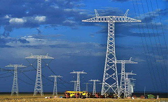
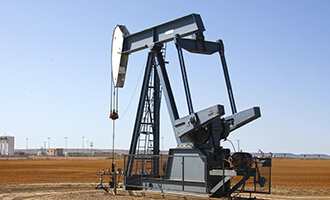
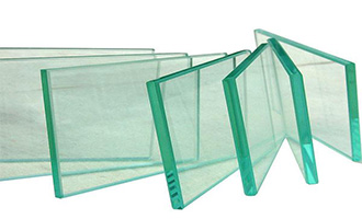
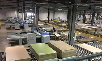
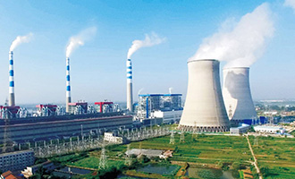
Thermal gas air flow meter widely use for Electric power, Petrochemical industry, Glass, Ceramics and Building materials industry, and mainly be used to meausre Dry gas, such as Air, Natural gas, LPG gas, Biogas, ect. But thermal gas mass flow couldn’d be used to measure Vapour, Humidity gas and Ethyne.
Water Treatment
Food Industry
Pharmaceutical Industry

Water Treatment
Food Industry
Pharmaceutical Industry
Technical Data
Table 1: Flange Thermal Gas Mass Flow Meter Parameter
|
Technical Specifications
|
||||||||||
|---|---|---|---|---|---|---|---|---|---|---|
|
Make
|
CBRO
|
|||||||||
|
Model
|
TMF1600 Series
|
|||||||||
|
Measuring Medium
|
Various Of Gas (Except Acetylene)
|
|||||||||
|
Pipe Size
|
(Insert connection) DN50-DN2000mm ,In-line connection(DN10-DN2000mm)
|
|||||||||
|
Velocity
|
0.1-100Nm/s
|
|||||||||
|
Accuracy
|
+/-1~2.5%
|
|||||||||
|
Working Temperature
|
Sensor:-40~+220 degC Transmitter:-20~+45 degC
|
|||||||||
|
Working Pressure
|
Insertion Sensor:medium pressure ≤1.6Mpa
Flanged Sensor:medium pressure ≤4.0Mpa
Special pressure please double check
|
|||||||||
|
Power Supply
|
Compact type: 24VDC or 220VAC, Power consumption ≤18W
Remote type:220VAC,Power consumption ≤19W
|
|||||||||
|
Response Time
|
1s
|
|||||||||
|
Output
|
4-20mA(optoelectronic isolation,maximum load 500Ω),Pulse RS485(optoelectronic isolation) and HART
|
|||||||||
|
Alarm Output
|
1-2 line Relay, Normally Open state, 10A/220V/AC or 5A/30V/DC
|
|||||||||
|
Sensor Type
|
Standard Insertion, Hot-tapped Insertion and Flanged
|
|||||||||
|
Construction
|
Compact and Remote
|
|||||||||
|
Pipe Material
|
Carbon Steel, Stainless Steel,Plastic etc.
|
|||||||||
|
Display
|
4 lines LCD Mass flow, Volume flow in standard condition, Flow totalizer, Date and Time, Working time, and Velocity, etc.
|
|||||||||
|
Protection
|
IP65
|
|||||||||
Table 2: Flange Thermal Gas Mass Flow Meter Sizing
|
Nominal Diameter
|
Flange outer diameter
|
Center hole
|
Bolt hole
|
Screw Threads
|
Sealing face
|
Flange thickness
|
Installation length
|
|
|---|---|---|---|---|---|---|---|---|
|
DN
|
D
|
k
|
n x L
|
|
d
|
f
|
C
|
L
|
|
15
|
95
|
65
|
4x14
|
M12
|
46
|
2
|
14
|
280
|
|
20
|
105
|
75
|
4x14
|
M12
|
56
|
2
|
16
|
280
|
|
25
|
115
|
85
|
4x14
|
M12
|
65
|
2
|
16
|
280
|
|
32
|
140
|
100
|
4x18
|
M16
|
76
|
2
|
18
|
350
|
|
40
|
150
|
110
|
4x18
|
M16
|
84
|
2
|
18
|
350
|
|
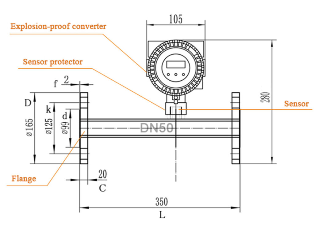
50
|
165
|
125
|
4x18
|
M16
|
99
|
2
|
20
|
350
|
|
65
|
185
|
145
|
4x18
|
M16
|
118
|
2
|
20
|
400
|
|
80
|
200
|
160
|
8x18
|
M16
|
132
|
2
|
20
|
400
|
|
100
|
220
|
180
|
8x18
|
M16
|
156
|
2
|
22
|
500
|
Table 3: Common Use Gas Maximum Range
|
Caliber ( mm )
|
Air
|
Nitrogen ( N2 )
|
Oxygen ( O2 )
|
Hydrogen ( H2 )
|
|---|---|---|---|---|
|
15
|
65
|
65
|
32
|
10
|
|
25
|
175
|
175
|
89
|
28
|
|
32
|
290
|
290
|
144
|
45
|
|
40
|
450
|
450
|
226
|
70
|
|
50
|
700
|
700
|
352
|
110
|
|
65
|
1200
|
1200
|
600
|
185
|
|
80
|
1800
|
1800
|
900
|
280
|
|
100
|
2800
|
2800
|
1420
|
470
|
|
125
|
4400
|
4400
|
2210
|
700
|
|
150
|
6300
|
6300
|
3200
|
940
|
|
200
|
10000
|
10000
|
5650
|
1880
|
|
250
|
17000
|
17000
|
8830
|
2820
|
|
300
|
25000
|
25000
|
12720
|
4060
|
|
350
|
45000
|
45000
|
22608
|
5600
|
|
400
|
70000
|
70000
|
35325
|
7200
|
|
450
|
100000
|
100000
|
50638
|
9200
|
|
500
|
135000
|
135000
|
69240
|
11280
|
|
600
|
180000
|
180000
|
90432
|
16300
|
|
700
|
220000
|
220000
|
114500
|
22100
|
|
800
|
280000
|
280000
|
141300
|
29000
|
|
900
|
400000
|
400000
|
203480
|
36500
|
|
1000
|
600000
|
600000
|
318000
|
45000
|
|
2000
|
700000
|
700000
|
565200
|
18500
|
Table 4: Flange Thermal Gas Mass Flow Meter Model Selection
|
Model
|
QTMF
|
X
|
X
|
X
|
X
|
X
|
X
|
X
|
||
|---|---|---|---|---|---|---|---|---|---|---|
|
Caliber
|
DN15-DN4000
|
|
|
|
|
|
|
|
||
|
Structure
|
Compact
|
C
|
|
|
|
|
|
|
||
|
Remote
|
R
|
|
|
|
|
|
|
|||
|
Senor type
|
Insertion
|
I
|
|
|
|
|
|
|||
|
Flange
|
F
|
|
|
|
|
|
||||
|
Clamp
|
C
|
|
|
|
|
|
||||
|
Screw
|
S
|
|
|
|
|
|
||||
|
Material
|
SS304
|
304
|
|
|
|
|
||||
|
SS316
|
316
|
|
|
|
|
|||||
|
Pressure
|
1.6Mpa
|
1.6
|
|
|
|
|||||
|
2.5Mpa
|
2.5
|
|
|
|
||||||
|
4.0Mpa
|
4.0
|
|
|
|
||||||
|
Teperature
|
-40-200℃
|
T1
|
|
|
||||||
|
-40-450℃
|
T2
|
|
|
|||||||
|
Power Supply
|
AC85~250V
|
AC
|
|
|||||||
|
DC24~36V
|
DC
|
|
||||||||
|
Signal Output
|
4-20mA+Pulse+RS485
|
RS
|
||||||||
|
4-20mA+Pulse+HART
|
HT
|
|||||||||
Installation
nge thermal gas mass flow meter installation:
① Observe the recommended inlet and outlet requirements.
② Good engineering practice is necessary for the associated pipe work and installation.
③ Ensure correct alignment and orientation of the sensor.
④ Take measures to reduce or avoid condensation (e.g. install a condensation trap, thermal insulation, etc.).
⑤ The maximum permitted ambient temperatures and the medium temperature range must be observed.
⑥ Install the transmitter in a shaded location or use a protective sun shield.
⑦ For mechanical reasons, and in order to protect the pipe, it is advisable to support heavy sensors.
⑧ No installation in where large vibration exists
⑨ No exposure in the environment containing a lot of corrosive gas
⑩ No sharing power supply with frequency converter, electric welding machine and other machines which can make power-line interference.
Daily maintenance for flange thermal gas mass flow meter:
In the daily operation of the thermal gas mass flowmeter, check and clean the flowmeter, tighten the loose parts, find and deal with the abnormality of the flowmeter in operation in time, ensure the normal operation of the flowmeter, reduce and delay the wear of components, Extend the service life of the flowmeter. Some flowmeters will become fouling after being used for a period of time, and it must be cleaned by pickling etc. depending on the degree of fouling
Other Products in 'Thermal Mass Flow Meter' category

SEND YOUR INQUIRY
Exported to more than 150 countries around the globe, 10000 sets/month production capacity!
OUR GLOBAL PRESENCE
Nature of business – MANUFACTURER , EXPORTER
- GULF COUNTRIES > UAE
- QATAR
- SAUDI ARABIA
- KUWAIT
- OMAN
- IRAQ
- IRAN
- BAHRAINS
- YEMEN
- JORDAN
- EGYPT
- RIYADH
- AUSTRAILIA
- NEWZELAND
- BANGLADESH
- NEPAL
- SRI LANKA
- AFGHANISTAN
- CYPRUS
- TURKEY
- SYRIA
- INDONESIA
- VITNAM
- PHILIPPINES
- ISRAEL
- MALAYASIA
- CAMBODIA
- PALESTINE
- South Africa
- Angola
- Botswana
- Lesotho
- Mozambique
- Namibia
- South Africa
- Swaziland
- Zambia
- UK
- BULGARIA
- BELGIUM
- Argentina
- Bolivia
- Brazil
- Chile
- Colombia
- Ecuador
- Ecuador
- Paraguay
- Peru
- Suriname
- Uruguay
- Venezuela
- South American Countries
- Brazil
- Columbia
- Chile
- Colombia