Product Categories


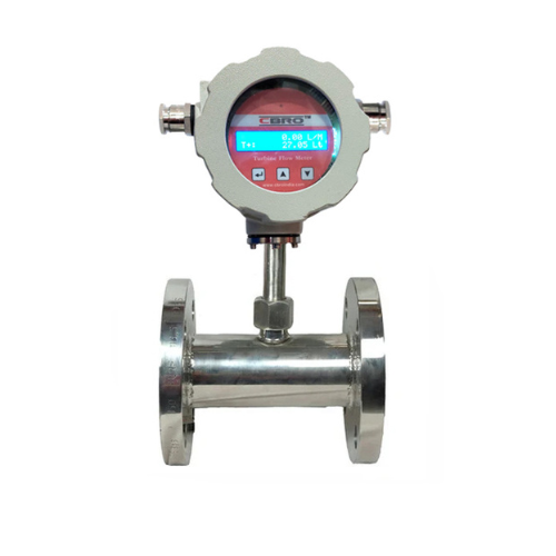
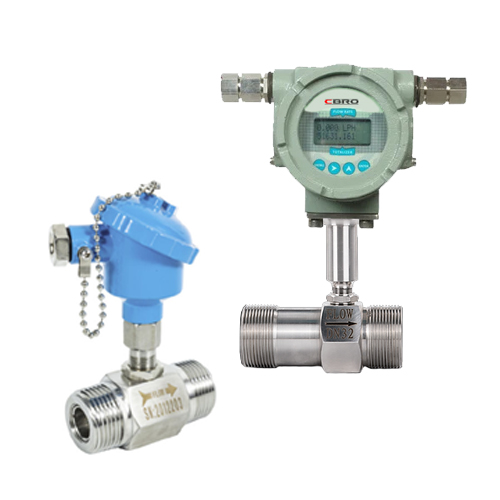
Sanitary Turbine Flow Meter
MODEL: TFM250 Series
CBRO Liquid Turbine Flow Meter is internally developed and perfected by CBRO Instrument. Over the years, CBRO Liquid Turbine Flow Meter has been commissioned in many parts of the world, received praise from end-users and industrial leaders.
CBRO Instrument Turbine Flow Meter offers two accuracy classes, 0.5%R and 0.2%R. Its simple structure allows a small pressure loss and virtually no maintenance requirements.
The Tri-Clamp Turbine Flow Meter offers two types of converter options, Compact Type (Direct Mount) and Remote Type. Our users can select the preferred converter type depending on the commissioning environment. CBRO Tri-Clamp Turbine flow meter popular turbine product used to measure clean oil and water.
Contact us


info@cbroindia.com sales@cbroindia.com

Sales Support
+917021306718
Technical Support
+918591988100
Application
CBRO Instrument Liquid Turbine Meters offers both standard SS304 body and SS316 body. Because of its wide working temperature and pressure range, it is capable of measuring various mediums and commissioning into extreme working conditions. It is the most popular turbine product in beverage factories, oil production and transportation, water supply, chemical injection and much more.
Due to its high accuracy and fast response time, CBRO Instrument Liquid Turbine is often integrated into the Industrial Internet of Things, together with valves and pumps to achieve smart process control, for example, solvents batching, blending, storage and off-loading systems. Kindly contact our sales engineers if there are questions integrating CBRO Liquid Turbine Meters into your existing plant IOT.
Water Treatment

Petrochemical

Chemical Monitoring

Upstream Oil Transportation

Off-shore Exploration
Water Supply
Technical Data
Table 1: Tri-Clamp Turbine Flow Meter Parameters
|
Technical Specifications
|
||||||||||
|---|---|---|---|---|---|---|---|---|---|---|
|
Make
|
CBRO
|
|||||||||
|
Model
|
MODEL: TFM250
Series
|
|||||||||
|
Accuracy
|
±0.5%, ±0.2% Optional
|
|||||||||
|
Size
|
DN4,6,10,15,20,32,40,50,65,80,100
|
|||||||||
|
Sensor Material
|
SS304, SS316L Optional
|
|||||||||
|
Ambient Conditions
|
Medium temperature:-20℃~+150℃
Atmospheric pressure:86Kpa~106Kpa
Ambient temperature:-20℃~+60℃
Relative humidity:5%~90%
|
|||||||||
|
Signal Output
|
Pulse, 4-20mA, Alarm(optional)
|
|||||||||
|
Digital Communication
|
RS485, HART
|
|||||||||
|
Power Supply
|
24V DC/3.6V Lithium Battery
|
|||||||||
|
Cable Entry
|
M20*1.5; 1/2"NPT
|
|||||||||
|
Explosion-proof class
|
Ex d IIC T6 Gb
|
|||||||||
|
Protection class
|
IP65
|
|||||||||
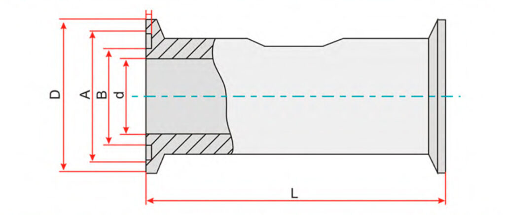
Table 2: Tri-Clamp Turbine Flow Meter Dimension
|
DN
|
D(mm)
|
A(mm)
|
B(mm)
|
d(mm)
|
L(mm)
|
|---|---|---|---|---|---|
|
DN4
|
50
|
45
|
40.5
|
4
|
100
|
|
DN6
|
50
|
45
|
40.5
|
6
|
100
|
|
DN10
|
50
|
45
|
40.5
|
10
|
100
|
|
DN15
|
50
|
45
|
40.5
|
15
|
100
|
|
DN20
|
50
|
45
|
40.5
|
20
|
100
|
|
DN25
|
50
|
45
|
40.5
|
25
|
100
|
|
DN32
|
50
|
45
|
40.5
|
32
|
100
|
|
DN40
|
64
|
59
|
54
|
40
|
140
|
|
DN50
|
77
|
73.5
|
68.5
|
50
|
150
|
Table 3: Tri-Clamp Turbine Flow Meter Flow Range
|
Diameter (mm)
|
Standard Range (m3/h)
|
Extended Range (m3/h)
|
Standard Pressure (Mpa)
|
|---|---|---|---|
|
DN4
|
0.04~0.25
|
0.04~0.4
|
1.6
|
|
DN6
|
0.1~0.6
|
0.06~0.6
|
1.6
|
|
DN10
|
0.2~1.2
|
0.15~1.5
|
1.6
|
|
DN15
|
0.6~6
|
0.4~8
|
1.6
|
|
DN20
|
0.8~8
|
0.45~9
|
1.6
|
|
DN25
|
1~10
|
0.5~10
|
1.6
|
|
DN32
|
1.5~15
|
0.8~15
|
1.6
|
|
DN40
|
2~20
|
1~20
|
1.6
|
|
DN50
|
4~40
|
2~40
|
1.6
|
|
DN65
|
7~70
|
4~70
|
1.6
|
|
DN80
|
10~100
|
5~100
|
1.6
|
Table 4: Liquid Turbine Flow Meter Model Selection
|
Model Suffix Code
|
Description
|
||||||||||||
|---|---|---|---|---|---|---|---|---|---|---|---|---|---|
|
LWGY-
|
XXX
|
X
|
X
|
X
|
X
|
X
|
X
|
X
|
X
|
|
|||
|
Diameter
|
|
|
|
|
|
|
|
Three Digitals; for example:
010: 10 mm; 015: 15 mm; 080: 80 mm; 100: 100 mm |
|||||
|
Converter
|
N
|
|
|
|
|
|
|
No display; 24V DC; Pulse Output
|
|||||
|
A
|
|
|
|
|
|
|
No display; 24V DC; 4-20mA Output
|
||||||
|
B
|
|
|
|
|
|
|
Local display; Lithium Battery Power; No output
|
||||||
|
C
|
|
|
|
|
|
|
Local display; 24V DC Power; 4-20mA Output;
|
||||||
|
C1
|
|
|
|
|
|
|
Local display; 24V DC Power; 4-20mA Output; Modbus RS485 Communication
|
||||||
|
C2
|
|
|
|
|
|
|
Local display; 24V DC Power; 4-20mA Output; HART Communication
|
||||||
|
Accuracy
|
05
|
|
|
|
|
|
0.5% of Rate
|
||||||
|
02
|
|
|
|
|
|
0.2% of Rate
|
|||||||
|
Flow Range
|
S
|
|
|
|
|
|
Standard Range: refer to flow range table
|
||||||
|
W
|
|
|
|
|
|
Wide Range: refer to flow range table
|
|||||||
|
Body Material
|
S
|
|
|
|
|
SS304
|
|||||||
|
L
|
|
|
|
|
SS316
|
||||||||
|
Explosion Rating
|
N
|
|
|
|
Safety Field without Explosion
|
||||||||
|
E
|
|
|
|
ExdIIBT6
|
|||||||||
|
Pressuring Rating
|
E
|
|
|
|
Per Standard
|
||||||||
|
H(X)
|
|
|
|
Customized Pressure Rating
|
|||||||||
|
Connection
|
-DXX
|
|
|
DXX: D06, D10, D16, D25, D40 D06: DIN PN6; D10: DIN PN10 D16: DIN PN16; D25: DIN PN25 D40: DIN PN40
|
|||||||||
|
-AX
|
|
|
AX: A1, A3, A6
A1: ANSI 150#; A3: ANSI 300#
A6: ANSI 600#
|
||||||||||
|
-JX
|
|
|
|
||||||||||
|
-TH
|
|
|
Thread; DN4…DN50
|
||||||||||
|
Fluid Temperature
|
-T1
|
-20...+80°C
|
|||||||||||
|
-T2
|
-20...+120°C
|
||||||||||||
|
-T3
|
-20...+150°C
|
||||||||||||
Installation
Tri-Clamp Turbine Flow Meter Installation and Maintenance
Before the installation, it is crucial to communicate with our sales engineers regarding the working conditions and medium the meter designs to measure.
The installation of the Q&T Tri-Clamp Liquid Turbine Meter involves minimal effort. Comes with the product, users will receive a pair of clamps. During installation, the users will not need additional tools for Tri-Clamp type Turbine Flow Meter.
The user needs to keep in mind these three factors while carrying out the installation.
1. There should be at least ten pipe diameter lengths of straight pipe upstream of the Turbine Meter and five pipe diameter length of straight pipe length downstream of the Turbine Meter, with the same nominal diameter size.
2. Valves and Throttling devices needed to install downstream of the flow meter.
3. The arrow indicated on the meter body is the same as the actual flow.
If there are specific questions regarding the installation of the Q&T Instrument Turbine Meter, kindly contact our sales engineers for assistance.
(1).jpg) One 90° elbow | .jpg) Two 90° elbows for two planes |
.jpg) Concentric expander | .jpg) Control valve half-open |
.jpg) Concentric shrinkage wide open valve | .jpg) Two 90° elbows for one plane |
Q&T Liquid Turbine Meter requires minimum maintenance.
Daily cleaning and inspection can be carried out by loosen the clamps and remove the Turbine Meter from the pipe.
Reinstallations are carried out similarly to the installation steps indicated above.
If the meter is damaged and repair is needed, kindly contact Q&T Instrument Sales Engineers.
Other Products in 'Turbine Flow Meter' category
SEND YOUR INQUIRY
Exported to more than 150 countries around the globe, 10000 sets/month production capacity!