
info@cbroindia.com sales@cbroindia.com

Sales Support
+917021306718
Technical Support
+918591988100


|
Technical Specifications
|
||||||||||
|---|---|---|---|---|---|---|---|---|---|---|
|
Make
|
CBRO
|
|||||||||
|
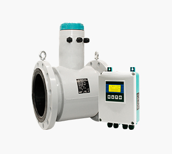
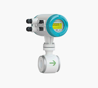
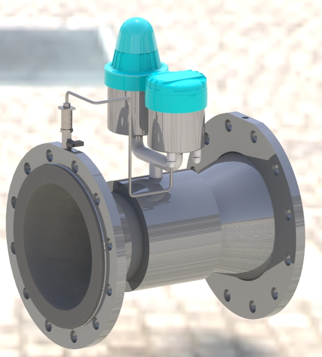
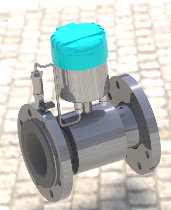
Model
|
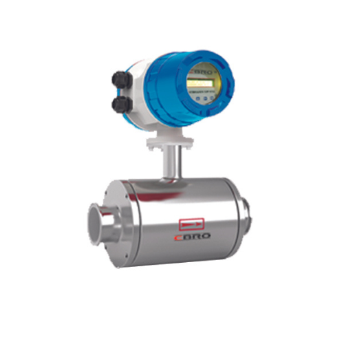
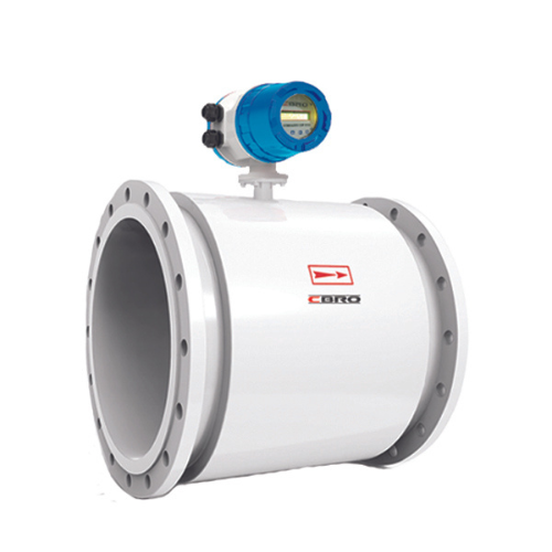
DIGIMAG250 Series
|
|||||||||
|
Flow direction
|
Positive/negative/net flow
|
|||||||||
|
Range Ratio
|
R160/250/400(Optional)
|
|||||||||
|
Accuracy Class
|
1 class/2 class(Optional)
|
|||||||||
|
Nominal Diameter(mm)
|
DN50
|
DN65
|
DN80
|
DN100
|
DN125
|
DN150
|
DN200
|
DN250
|
DN300
|
|
|
Nominal Flow Rate(m3/h)
|
40
|
63
|
100
|
160
|
250
|
400
|
630
|
1000
|
1600
|
|
|
Pressure Loss
|
∆P40
|
|||||||||
|
Temperature
|
T50
|
|||||||||
|
Pressure
|
1.6MPa(Special pressure can be customized)
|
|||||||||
|
Conductivity
|
≥20μS/cm
|
|||||||||
|
Initial flow velocity
|
5mm/s
|
|||||||||
|
Output
|
4-20mA, Pulse
|
|||||||||
|
Flow profile sensitivity class
|
U5,D3
|
|||||||||
|
Electromagnetic compatibility
|
E2
|
|||||||||
|
Connection Type
|
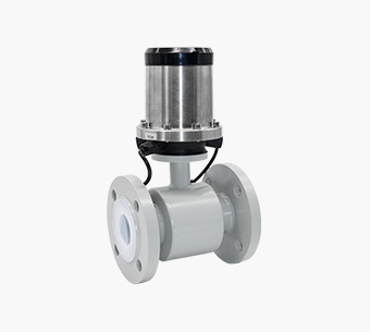
Flanged,GB/T9119-2010
|
|||||||||
|
Protection
|
IP68
|
|||||||||
|
Ambient temperature
|
-10℃~+75℃
|
|||||||||
|
Relative humidity
|
5%~95%
|
|||||||||
|
Installation type
|
Horizontal and vertical
|
|||||||||
|
Electrode material
|
316L
|
|||||||||
|
Body material
|
Carbon steel/ stainless steel (optional)
|
|||||||||
|
Grounding method
|
With or without grounding/grounding ring/grounding electrode (optional)
|
|||||||||
|
Product Selection
|
 Base
Base
|
 Wireless IOT
|
 Wireless remote transmission of flow and pressure
|
 Remote transmission of flow and pressure
|
||||||
|
Output
|
/
|
GPRS/Nbiot
|
GPRS/ Nbiot/Pressure remote
|
RS485/TTL
|
||||||
|
Communication
|
/
|
CJT188,MODBUS
|
CJT188,MODBUS
|
CJT188,MODBUS
|
||||||
|
Power Supply
|
DC3.6V Lithium battery
|
DC3.6V Lithium battery
|
DC3.6V Lithium battery
|
DC3.6V Lithium battery
|
||||||
|
Structure Type
|
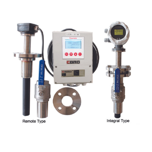
Integral and remote type
|
Integral and remote type
|
Integral and remote type
|
Integral and remote type
|
||||||
|
Units
|
Accumulated flow:m3
Instantaneous flow:m3/h
|
Accumulated flow:m3
Instantaneous flow:m3/h
|
Accumulated flow:m3
Instantaneous flow:m3/h Pressure:MPa
|
Accumulated flow:m3
Instantaneous flow:m3/h
|
||||||
|
Application
|
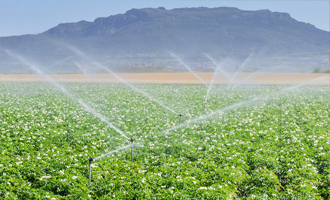
Can replace water meter, ultra-low pressure loss, no wear
|
Real-time and effective remote meter reading
|
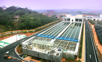
Realize pipe network pressure monitoring and become an intelligent terminal for metering and monitoring to provide information for the water supply enterprise informatization construction (SCADA,GIS,modeling, hydraulic model,scientific dispatch)
|
Wired remote
|
||||||
Installation environment selection
1. Stay away from devices with strong electromagnetic fields. Such as large motor, large transformer, large frequency conversion equipment.
2. The installation site should not have strong vibration, and the ambient temperature does not change much.
3. Convenient for installation and maintenance.
Selection of installation location
1. The flow direction mark on the sensor must be consistent with the flow direction of the measured medium in the pipeline.
2. The installation position must ensure that the measuring tube is always filled with the measured medium.
3. Select the place where the fluid flow pulse is small, that is, it should be far away from the water pump and local resistance parts (valves, elbows, etc.)
4. When measuring the two-phase fluid, choose the place which is not easy to cause phase separation.
5. Avoid installation in the area with negative pressure in the tube.
6. When the measured medium easily causes the electrode and the inner wall of the measuring tube to adhere to and scale, it is recommended that the flow rate in the measuring tube be no less than 2m/s. At this time, a tapered tube slightly smaller than the process tube can be used. In order to clean the electrode and measuring tube without interrupting the flow in the process tube, the sensor can be installed in parallel with a cleaning port.
Upstream straight pipe section requirements
The requirements of the sensor on the upstream straight pipe section are shown in the table. When the diameters of the upstream and downstream straight pipe sections are inconsistent with those of the electromagnetic cold water meter, the tapered pipe or the tapered pipe should be installed, and its conical Angle should be less than 15° (7° -8 ° is preferred) and then connected with the pipe.
less than 15° (7° -8 ° is preferred) and then connected with the pipe.
| Upstream resistance components | .jpg) Note: L is straight pipe length | .jpg) | .jpg) |
| Straight pipe requirements | L=0D can be considered as a straight pipe section | L≥5D | L≥10D |
Note :(L is the length of straight pipe section, D is the nominal diameter of sensor)