Product Categories


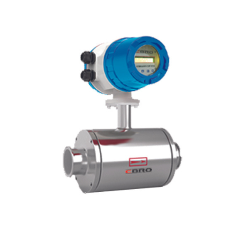
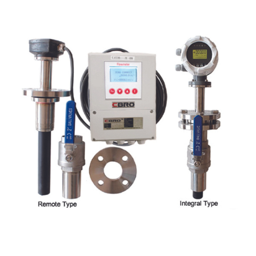
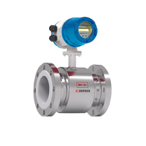
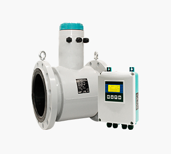
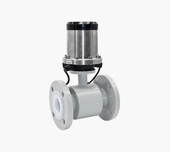
Wafer Electromagnetic Flow Meter
MODEL: DIGIMAG250 Series
Wafer electromagnetic flow meter is a kind of volume flow meter. It uses a new generation of special high-quality lining technology and a special mirror-polished PFA lining, which is especially suitable for the measurement of viscous pulp and gypsum slurry. Its detachable electrode makes maintenance more convenient. Principle of Wafer electromagnetic flow meter : The product is based on Faraday’s law of electromagnetic induction, conductance greater than 20 μS/cm volume of conductive liquid flow. In addition to measuring the general volume of conductive liquid flow, but also can be used to measure strong acid, alkali and other strong corrosive liquids and mud, pulp, etc.
Contact us


info@cbroindia.com sales@cbroindia.com

Sales Support
+917021306718
Technical Support
+918591988100
Advantages
Wafer Electromagnetic Flow Meter Advantages and Disadvantages
Wafer electromagnetic flow meter has short body, it can be installed in narrow areas such as well, ditch, irrigation pipe, etc.
It matches all flanges like ANSI, DIN, JIS, etc. So if you don’t know the flange standards, you can choose this type.
And wafer electromagnetic flow meter adopts harmless and durable stainless steel as raw material(SS304 or SS316), so it can be used for drinking water, underground water, etc. For food grade measurement, we suggest customer use SS316 material.
Wafer electromagnetic flow meter is easy to delivery, save your freight fee. Not only its body is short and thin, but its weight is also very light.
Application
Wafer Electromagnetic Flow Meter Application
Electromagnetic flow meter is widely used in water treatment, food industry, pharmaceutical, petrochemical, paper mill, chemical monitoring etc.
In the metallurgical industry, it is often used to control the flow of cooling water for continuous steel casting, continuous steel rolling, and steel-making electric furnaces;
In the field of water supply and drainage in public utilities, electromagnetic flow meters are often used for the transfer measurement of finished product water and raw water in water plants;
In the pulp process of the paper industry, electromagnetic flow meters are involved in the measurement of the flow of grinding pulp, water, acid, and alkali;
In the coal industry, measuring coal washing and pipeline hydraulic conveying coal slurry.
For food and beverage industries, it is used for beer and beverage filling measurement.
For chemical and petrochemical industries, it is used to measure corrosive liquids, such as acids and alkalis etc.

Water Treatment

Food Industry

Pharmaceutical Industry

Petrochemical
Paper Industry

Chemical Monitoring

Metallurgical Industry
Public Drainage

Coal Industry
Technical Data
Table 1: Wafer Electromagnetic Flow Meter Specification
|
Technical Specifications
|
||||||||||
|---|---|---|---|---|---|---|---|---|---|---|
|
Make
|
CBRO
|
|||||||||
|
Model
|
DIGIMAG250 Series
|
|||||||||
|
SIZE
|
DN25MM-DN200MM
|
|||||||||
|
Nominal Pressure
|
1.6Mpa
|
|||||||||
|
Accuracy
|
±0.5%(Standard)
±0.3% or ±0.2%(Optional)
|
|||||||||
|
Liner
|
PTFE, FEP, PFA
|
|||||||||
|
Electrode
|
SUS316L, Hastelloy B, Hastelloy C,
Titanium, Tantalum, Platinum-iridium
|
|||||||||
|
Structure Type
|
Integral type, remote type, submersible type, ex-proof type
|
|||||||||
|
Medium Temperature
|
-20~+60degC(Integral type)
|
|||||||||
|
Remote type(PTFE/PFA/FEP) -10~+160degC
|
||||||||||
|
Ambient Temperature
|
-20~+60degC
|
|||||||||
|
Ambient Humidity
|
5~90%RH(relative humidity)
|
|||||||||
|
Measuring Range
|
0.5m/s-15m/s
|
|||||||||
|
Conductivity
|
>5us/cm
|
|||||||||
|
Protection Class
|
IP65(Standard); IP68(Optional for remote type)
|
|||||||||
|
Output Signal
|
4-20mA, pulse/frequency, relay
|
|||||||||
|
Communication
|
MODBUS RTU RS485, HART(Optional), GPRS/GSM(Optional)
|
|||||||||
|
Power Supply
|
AC220V(Can be used for AC85-250V)
DC24V(Can be used for DC20-36V)
DC12V(Optional),Battery Powered 3.6V(Optional)
|
|||||||||
|
Power Consumption
|
<20W
|
|||||||||
|
Explosion Proof
|
ATEX Exdll T6Gb
|
|||||||||
Table 2: Wafer Electromagnetic Flow Meter Flow Range
|
Size
|
Flow Range & Velocity Table
|
|||||||
|---|---|---|---|---|---|---|---|---|
|
(mm)
|
0.1m/s
|
0.2m/s
|
0.5m/s
|
1m/s
|
4m/s
|
10m/s
|
12m/s
|
15m/s
|
|
25
|
0.177
|
0.353
|
0.883
|
1.766
|
7.065
|
17.663
|
21.2
|
26.494
|
|
32
|
0.289
|
0.579
|
1.447
|
2.894
|
11.575
|
28.938
|
34.73
|
43.407
|
|
40
|
0.452
|
0.904
|
2.261
|
4.522
|
18.086
|
45.216
|
54.26
|
67.824
|
|
50
|
0.707
|
1.413
|
3.533
|
7.065
|
28.260
|
70.650
|
84.78
|
105.98
|
|
65
|
1.19
|
2.39
|
5.97
|
11.94
|
47.76
|
119.40
|
143.3
|
179.10
|
|
80
|
1.81
|
3.62
|
9.04
|
18.09
|
72.35
|
180.86
|
217.0
|
271.30
|
|
100
|
2.83
|
5.65
|
14.13
|
28.26
|
113.04
|
282.60
|
339.1
|
423.90
|
|
125
|
4.42
|
8.83
|
22.08
|
44.16
|
176.63
|
441.56
|
529.9
|
662.34
|
|
150
|
6.36
|
12.72
|
31.79
|
63.59
|
254.34
|
635.85
|
763.0
|
953.78
|
|
200
|
11.3
|
22.61
|
56.52
|
113.04
|
452.16
|
1130.40
|
1356
|
1696
|
|
Suggest Velocity: 0.5m/s - 15m/s
|
||||||||
Table 3: Wafer Electromagnetic Flow Meter Size
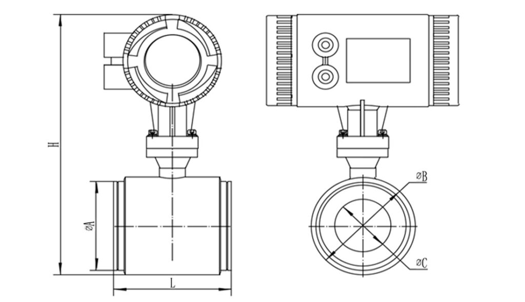
|
Diameter
|
φA(mm)
|
φB(mm)
|
φC(mm)
|
H(mm)
|
L(mm)
|
|---|---|---|---|---|---|
|
DN25
|
60.5
|
68
|
22
|
295
|
100
|
|
DN32
|
68.5
|
76
|
30
|
303
|
100
|
|
DN40
|
74.5
|
89
|
36
|
316
|
100
|
|
DN50
|
90.8
|
102
|
48
|
329
|
100
|
|
DN65
|
109.8
|
119.5
|
64
|
346.5
|
150
|
|
DN80
|
120.7
|
133
|
77
|
360
|
150
|
|
DN100
|
150.2
|
159
|
102
|
386
|
150
|
|
DN125
|
174.8
|
190
|
121
|
417
|
200
|
|
DN150
|
204.7
|
219
|
147
|
446
|
200
|
|
DN200
|
257.8
|
273
|
207
|
500
|
200
|
Table 4: Wafer Electromagnetic Flow Meter Selection
|
QTLD
|
|
XXX
|
X
|
X
|
X
|
X
|
X
|
X
|
X
|
X
|
||
|---|---|---|---|---|---|---|---|---|---|---|---|---|
|
Caliber
|
DN25mm-DN200mm
|
1
|
|
|
|
|
|
|
|
|
||
|
Nominal Pressure
|
1.6Mpa
|
1
|
|
|
|
|
|
|
|
|||
|
Connection mode
|
Clamp connection
|
1
|
|
|
|
|
|
|
||||
|
Liner material
|
PTFE
|
1
|
|
|
|
|
|
|||||
|
FEP
|
2
|
|
|
|
|
|
||||||
|
PFA
|
3
|
|
|
|
|
|
||||||
|
Electrode material
|
316L
|
1
|
|
|
|
|
||||||
|
Hastelloy B
|
2
|
|
|
|
|
|||||||
|
Hastelloy C
|
3
|
|
|
|
|
|||||||
|
Titanium
|
4
|
|
|
|
|
|||||||
|
Platinum-iridium
|
5
|
|
|
|
|
|||||||
|
Tantalum
|
6
|
|
|
|
|
|||||||
|
Stainless steel covered with tungsten carbide
|
7
|
|
|
|
|
|||||||
|
Electrode material
|
Integral type
|
1
|
|
|
|
|||||||
|
Remote type
|
2
|
|
|
|
||||||||
|
Remote type immerse
|
3
|
|
|
|
||||||||
|
Integral type Ex-proof
|
4
|
|
|
|
||||||||
|
Remote type Ex-proof
|
5
|
|
|
|
||||||||
|
Power
|
220VAC
|
E
|
|
|
||||||||
|
24VDC
|
G
|
|
|
|||||||||
|
output communication
|
Flow volume 4-20mADC/pulse
|
A
|
|
|||||||||
|
Flow volume 4-20mADC/RS232 communication
|
B
|
|
||||||||||
|
Flow volume 4-20mADC/RS485 communication
|
C
|
|
||||||||||
|
Flow volume HART output/with communication
|
D
|
|
||||||||||
|
Converter figure
|
Square
|
A
|
||||||||||
|
Circular
|
B
|
|||||||||||
Installation
Wafer Electromagnetic Flow Meter Installation & Maintainance
1. Installation
First of all, we need choose a pair of matching flanges. Then connect the flow meter with pipeline.
Wafer electromagnetic flow meter should be installed correctly to ensure good measurement. Normally we need leave 10D(10 times of diameter) straight pipe distance before wafer electromagnetic flow meter and 5D behind wafer electromagnetic flow meter.
And try to avoid elbow/valve/pump or other device which will influent the flow speed. If the distance is not enough, then please install flow meter according to follow picture.
.jpg) lnstall at the lowest point and vertical upward direction Don’t install at the highest point or vertical downward diection | .jpg) When drop is more than 5m, install exhaust valve at the downstream |
.jpg) lnstall at the lowest point when used in open drain pipe | .jpg) Need 10D of upstream and 5D of downstream |
.jpg) Dont’ install it at the entrance of pump, install it at the exit of pump | .jpg) lnstall at the rising direction |
2. Maintenance
Routine maintenance: only need to make periodic visual inspections of the instrument, check the environment around the instrument, remove dust and dirt, ensure that no water and other substances enter, check whether the wiring is in good condition, and check whether there are newly installed strong electromagnetic field equipment or newly installed wires near the instrument Cross-instrument. If the measuring medium easily contaminates the electrode or deposits in the measuring tube wall, it should be cleaned and cleaned regularly.
Other Products in ' Electromagnetic Flow Meter' category

SEND YOUR INQUIRY
Exported to more than 150 countries around the globe, 10000 sets/month production capacity!